
The suitability of each route and parking arrangement depends on the approved layout, circulation, ceiling interfaces and operating sequence. Project teams need to know which drawings specify the interface between the partition’s perimeter seals and wall-mounted devices such as emergency light test switches. This article provides an evidence-bounded framework for overseas contractors, architects, and building owners to coordinate these elements without relying on unsupported assumptions.
Understanding the Role of Drawings in Partition Seal Coordination
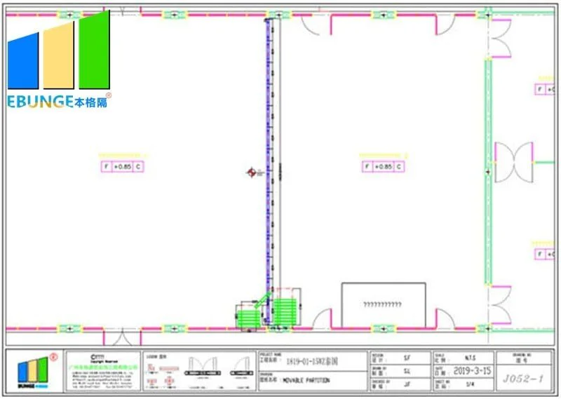
Drawings are the primary communication tool for integrating a movable partition with building services. They convey the intended layout, track routes, stacking positions, and interface details. For school auditorium partitions, the drawings must clearly indicate where seals meet walls, columns, and ceiling, and how wall-mounted items like emergency light test switches are positioned relative to the partition’s travel path and sealing surfaces.
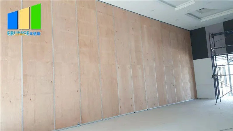
EBUNGE movable partition panels are individually movable, suspended from a top track, and cross the opening without a floor track. This design means that the floor remains clear, but the wall and ceiling interfaces are critical. The exact route, junction arrangement, continuous overhead path and parking position must be confirmed from the coordinated project drawings. The presence of a wall-mounted emergency light test switch near the partition’s parking or sealing zone requires careful coordination to avoid interference with panel movement or seal compression.
Key Drawing Types for Partition and Service Integration
Architectural Layout Drawings
Architectural plans show the partition’s location, opening dimensions, and stacking pocket. These drawings should indicate the clearance around the partition, including any wall-mounted devices. For a school auditorium, the layout must account for the emergency light test switch, which is often placed near doors or at accessible heights. The drawings should show the switch’s location relative to the partition’s travel path and stacking area, ensuring that panels do not obstruct access to the switch or vice versa.
Reflected Ceiling Plans (RCP)
The RCP is essential for showing the top track suspension and any ceiling-mounted equipment. Since EBUNGE panels are top-hung, the RCP must detail the track support structure and its integration with the ceiling grid. If an emergency light test switch is wall-mounted, the RCP may not directly show it, but the wall elevation details will. Coordination between RCP and wall elevations is necessary to ensure that the track does not conflict with the switch’s electrical conduit or mounting height.
Share the opening dimensions, room layout and intended operating sequence for review.
Wall Elevation and Section Details
Wall elevations and sections are where the seal interfaces are most clearly specified. These drawings show how the partition’s vertical seals meet the wall surface and how the top seal meets the ceiling. If a wall-mounted emergency light test switch is located within the seal’s compression zone, the drawings must indicate the switch’s dimensions and the seal’s deflection range. This ensures that the switch does not obstruct the seal or get damaged when the panel is moved.
What Information Do Drawings Need to Include for Seals at Test Switches?
To specify partition seals correctly at locations with wall-mounted devices, the following information should be included in the project drawings:
- Exact switch location: Height, horizontal position, and projection from the wall.
- Seal profile and compression: The type of seal (e.g., perimeter gasket) and its required compression range. This is generic; specific materials are not assumed.
- Clearance zones: The area around the switch that must remain free for seal contact and panel movement.
- Electrical conduit routing: How the switch’s wiring is routed within the wall to avoid interfering with the partition’s anchoring or track supports.
- Mounting details: Whether the switch is surface-mounted or recessed, and any required backing plates.
These details are typically found in architectural and electrical drawings. The project team must review them together to ensure consistency. EBUNGE’s project documentation can be discussed to clarify how the partition’s seals interact with such wall-mounted elements, but the final specifications depend on the specific project layout and requirements.
Coordination Between Partition Supplier and Electrical Consultant
Effective coordination between the partition supplier and the electrical consultant is vital. The electrical consultant designs the emergency lighting system, including test switches. The partition supplier provides the partition’s layout and seal details. Both parties must exchange drawings and mark-ups to resolve conflicts.
For example, if the test switch is located where the partition’s vertical seal will compress against the wall, the switch might need to be relocated or recessed. Alternatively, the seal profile might be adjusted to accommodate the switch. These decisions must be documented in the drawings and approved by all stakeholders.
EBUNGE’s team can review the proposed layout and provide input on how the partition’s movement and sealing might be affected. However, any specific modifications to the switch or seal must be confirmed through project-specific engineering review.
Acoustic Considerations at Wall-Mounted Devices
Visible references can support layout discussion but do not verify hidden construction or performance. The drawings must specify how the seal achieves continuous contact around the switch, or how the switch is integrated into the wall to maintain the seal’s integrity.
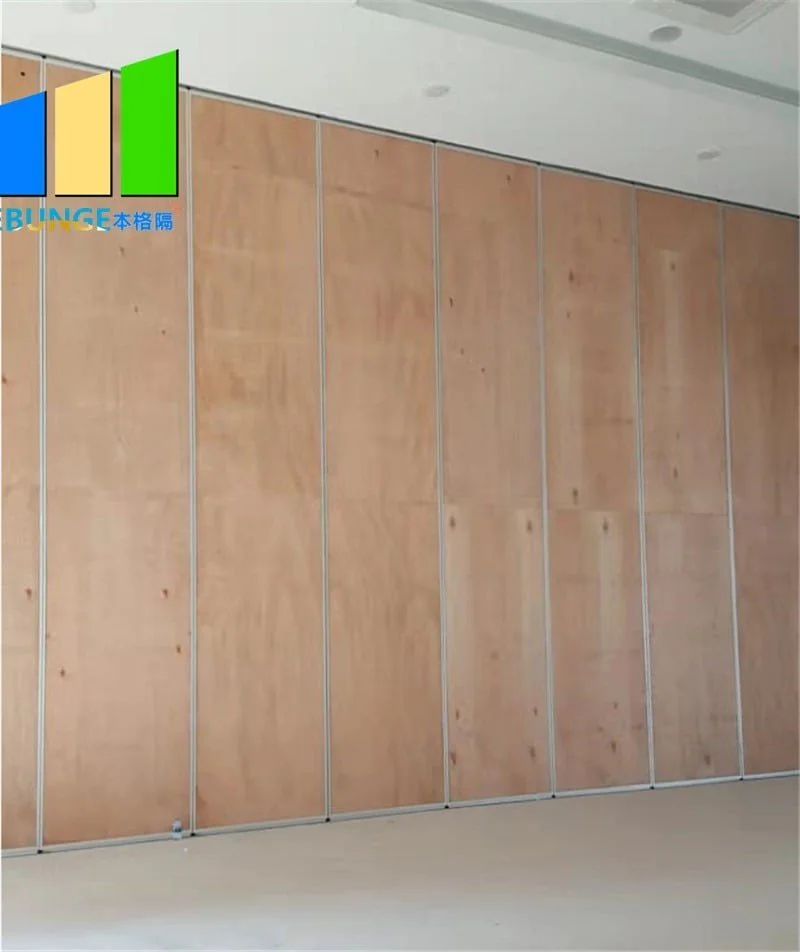
These ratings are determined through laboratory tests and are not directly translatable to on-site performance.
Stacking and Parking Routes: Impact on Switch Placement
EBUNGE movable partitions park at a planned stacking position. The stacking area is where panels are stored when the partition is open. This area must be free of obstructions, including wall-mounted devices. The drawings should clearly show the stacking route and the clearance required for panels to move into the stack.
If an emergency light test switch is located near the stacking area, it could interfere with panel movement or be damaged by panels. The layout drawings must ensure that the switch is placed outside the required clearance envelope.
Review the ceiling interface, panel route and stacking position together.
The drawings must show the radius and clearance needed for panels to turn. Wall-mounted devices in these areas should be avoided or recessed.
Documentation and Submittals for Procurement
During procurement, the project team should request and review the following documents from the partition supplier:
- Layout drawings showing the partition’s plan, elevation, and section details.
- Track and suspension details indicating the overhead support structure.
- Seal details at all perimeter interfaces, including walls, ceiling, and floor (though floor is clear).
- Stacking and parking details showing the storage configuration.
- Coordination drawings with electrical and mechanical services.
These documents should be reviewed for consistency with the architectural and electrical drawings. Any discrepancies should be resolved before fabrication. EBUNGE can provide project-specific documentation upon request, but the final approval rests with the project’s design team.
Common Pitfalls and How to Avoid Them
Ignoring the Switch’s Projection
Surface-mounted switches project from the wall. If the seal is designed to compress against a flat wall, a protruding switch can create a gap. The drawings must account for the switch’s depth and either recess it or adjust the seal.
Placing the Switch in the Stacking Area
Placing a switch where panels stack can obstruct movement or be damaged.
Lack of Coordination Between Disciplines
Without proper coordination, the electrical consultant may place the switch without knowing the partition’s seal requirements. Regular drawing reviews and clash detection can prevent this.
FAQ: School Auditorium Partition Seals and Emergency Light Test Switches
What drawings are needed to specify partition seals at a wall-mounted emergency light test switch?
Architectural wall elevations, sections, and electrical layout drawings are essential. They must show the switch’s exact location and the seal’s interface. Coordination drawings that overlay partition and electrical details are also recommended.
Can a wall-mounted emergency light test switch be located within the partition’s seal compression zone?
It is possible if the switch is recessed or the seal is designed to accommodate it. Project-specific review is necessary.
How does the absence of a floor track affect the placement of wall-mounted devices?
Since EBUNGE partitions do not require a floor track, the floor is clear. Wall-mounted devices are only a concern if they interfere with the panel’s vertical movement or stacking. The top track and wall seals are the primary interfaces.
What information should be included in the submittal drawings for the partition?
Submittals should include layout plans, elevations, sections, track details, seal profiles, and stacking configurations. Any coordination with electrical services should be clearly indicated.
Do I need to provide the partition supplier with the electrical drawings?
Yes, sharing electrical drawings helps the supplier identify potential conflicts and propose solutions. Cost and maintenance requirements depend on the selected configuration, finish and project conditions and require project-specific confirmation.
Conclusion and Next Steps
Coordinating school auditorium partition seals with wall-mounted emergency light test switches requires a thorough review of project drawings and early collaboration between all parties. The exact overhead route and support arrangement must be confirmed by the responsible project team from coordinated drawings.
For your next project, discuss your specific layout and requirements with EBUNGE. Our team can review your drawings and provide guidance on partition configuration, including seal details and stacking routes. Contact EBUNGE to start the conversation. For more examples, visit our project portfolio.
Continue Exploring
More Acoustic Partition Guides
- Newer guideWhat Maintenance Inspection Checklist Applies to Restaurant Partition Seals at Floor-Mounted Grease Trap Covers
- Earlier guideAuditorium Partition Seal Planning Near Acoustic Absorber Edges
- Related guideHow to Coordinate Office Meeting Suite Partition Seals with Wall-Mounted Video Bar Swing Paths
- Related guideHow to Coordinate Hotel Banquet Partition Seals with Ceiling-Mounted Rigging Point Access Panels