When planning a university training center, the integration of university training center partition stacking drawings projector lifts is a critical coordination task. These spaces often require flexible room configurations, where movable walls divide large halls into smaller seminar rooms or training suites. The drawings must clearly show how the wall panels stack at designated parking positions, while ceiling-mounted projector lifts are coordinated to avoid conflicts. For procurement teams, understanding these drawings is essential to ensure the movable wall system meets the pedagogical and spatial demands of the institution.
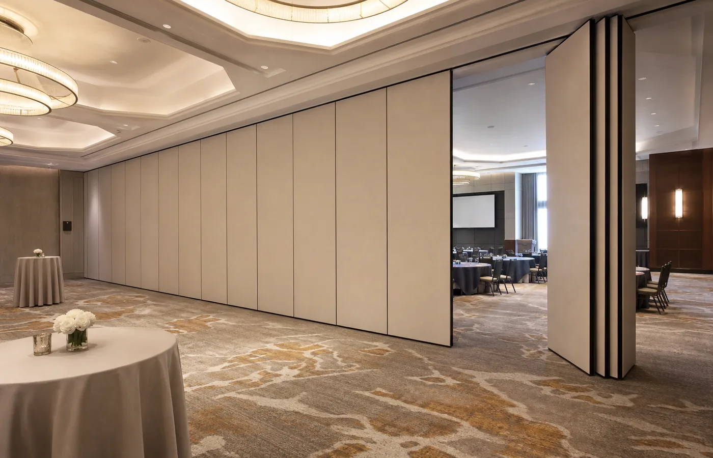
Movable walls, also known as operable partitions, are individually movable panels suspended from a top track. They cross the opening without a floor track, which is a significant advantage in university settings where floor finishes and accessibility are priorities. The panels park at a planned stacking position, which must be precisely indicated in the architectural drawings. This article explains what those drawings specify, how they relate to ceiling-mounted projector lifts, and what procurement professionals should look for when reviewing project documentation.
Understanding Movable Wall Systems in Training Centers
Movable wall systems are engineered to provide flexibility in large spaces. In a university training center, they allow the subdivision of a large hall into multiple smaller rooms for workshops, seminars, or examinations. The key components of a movable wall system include top-hung panels, a ceiling-suspended track, and a stacking area. The panels are manually operated, and their movement is guided by the track system. The absence of a floor track means the floor remains unobstructed, which is beneficial for cleaning, accessibility, and reconfiguration.

Key Components and Their Role in Drawings
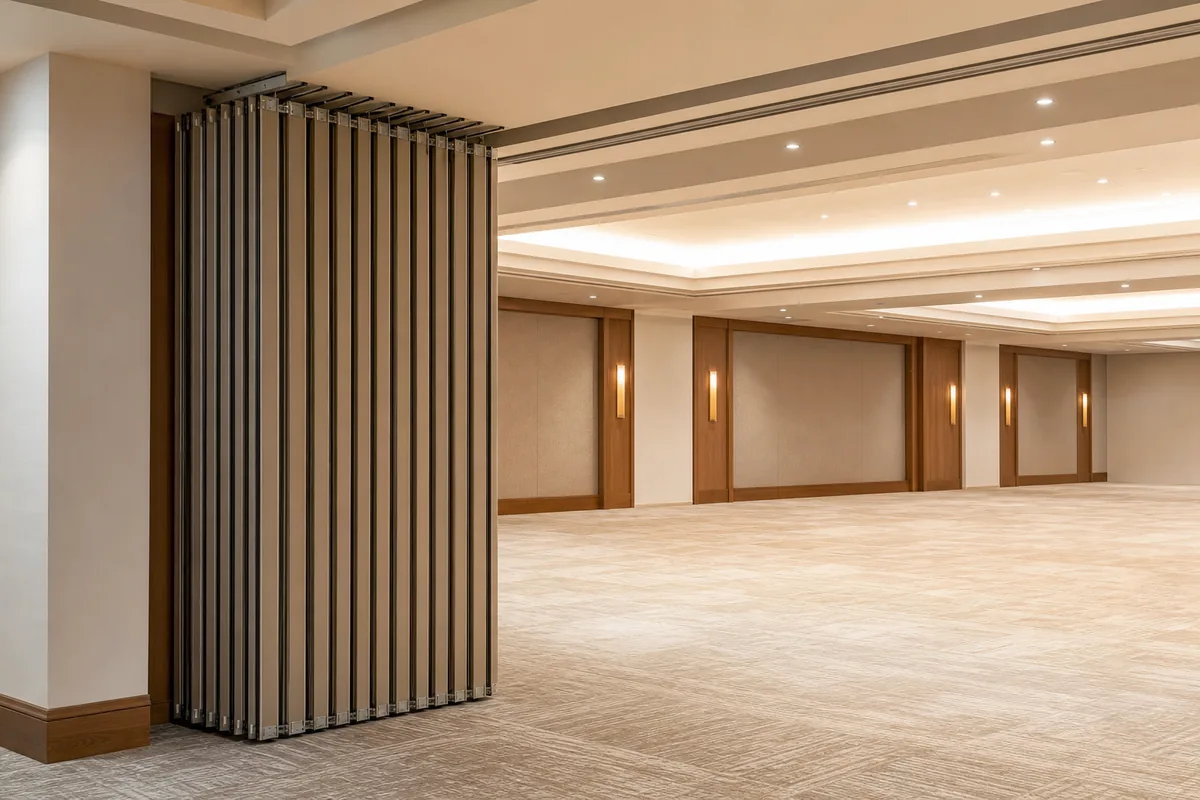
The drawings for a movable wall installation must clearly identify the top track, the panels, and the stacking zone. The top track is the structural element from which the panels are suspended. It must be engineered to support the weight of the panels and to guide their movement smoothly. The stacking zone is the area where the panels are stored when not in use. It is typically located at one end of the opening or in a recess designed for this purpose. The drawings must show the dimensions of the stacking zone, the number of panels, and the clearances required for safe operation.
The Role of Stacking Routes in Layout Drawings
Stacking routes are the paths that the panels follow when being moved from the closed position to the stacking area. These routes can be straight, turning, or a combination of both, depending on the building layout. The drawings must review these routes to ensure they are feasible and do not conflict with other building elements, such as columns, doors, or ceiling-mounted equipment. For university training centers with projector lifts, the stacking route must be coordinated to avoid interference with the lift mechanisms.
Share the opening plan, stacking position and fixed obstructions.
Straight Stacking Routes
Straight stacking routes are the simplest and most common. The panels move in a linear direction from the opening to the stacking area. This requires adequate linear space along the track. The drawings must show the length of the track, the position of the stacking area, and the clearances at both ends. For straight routes, the stacking area is often an extension of the track, allowing the panels to be pushed together.
Turning Stacking Routes
Turning routes involve a curve or a switch in the track to redirect the panels. This is common in spaces where the stacking area is perpendicular to the opening. The drawings must indicate the radius of the curve, the number of panels that can be accommodated, and the additional space required for the turning motion. Turning routes require careful planning to ensure the panels do not derail or jam.
Coordinating with Ceiling-Mounted Projector Lifts
Ceiling-mounted projector lifts are common in university training centers to provide flexible audiovisual setups. These lifts lower the projector from the ceiling when needed and retract it when not in use. The drawings must coordinate the location of these lifts with the movable wall system, especially the stacking area and the track path. If a projector lift is positioned directly above the stacking area, it might interfere with the vertical clearance required for the panels.
Clearance and Interference Checks
The drawings must show the vertical clearance between the top of the movable wall panels and the bottom of the projector lift when it is in the retracted position. Typically, a clearance of at least 100 mm is recommended, but this should be confirmed with the manufacturers. Additionally, the track path must avoid any ceiling-mounted equipment that could obstruct the movement of the panels. The drawings should include section views that clearly show the relationship between the track, the panels, and the projector lift.
Electrical and Data Considerations
Projector lifts require electrical power and data connections. These services are often routed in the ceiling. The drawings must show the location of junction boxes, conduits, and data outlets relative to the movable wall track. This ensures that the installation of the movable wall does not damage existing services and that future maintenance is possible.
Acoustic Performance in Training Center Partitions
In a university training center, acoustic performance is crucial to ensure that simultaneous sessions do not interfere with each other. Movable walls are designed to provide sound insulation, but the actual performance depends on many factors, including the seals around the panels and the construction of the surrounding structure. Drawings must specify the acoustic requirements, such as the desired Sound Transmission Class (STC) or Weighted Sound Reduction Index (Rw). These ratings indicate how much sound is reduced when passing through the partition. However, they do not directly translate to a specific number of decibels in all situations.
Seals and Perimeter Sealing
The drawings must detail the perimeter sealing of the movable wall, including the top, bottom, and vertical seals between panels. These seals are essential for achieving the acoustic performance. The type of seal material and its installation method should be specified. However, the exact material and performance data should be confirmed with the manufacturer, as they depend on the specific project conditions.
Acoustic Testing and Verification
It is recommended that the drawings include a note stating that acoustic performance should be verified through on-site testing after installation. This ensures that the installed system meets the specified requirements. The drawings should also indicate any acoustic seals that need to be adjusted or replaced over time to maintain performance.
Review the full panel route and parking footprint.
Pass Doors in Movable Walls
In many training centers, it is necessary to have a pass door within the movable wall to allow entry and exit without moving the entire partition. The drawings must specify the location, size, and swing direction of the pass door. The pass door must be integrated into the panel design, and its hardware must be coordinated with the overall system.
Integration with Stacking
The pass door adds complexity to the stacking process. When the wall is being stacked, the door must be closed and secured. The drawings must show how the door is handled during stacking and whether it requires any special mechanism. This is particularly important when the stacking route is tight or involves turning.
Documentation and Approval Process
For procurement, the drawings are part of the project documentation that must be reviewed and approved. The drawings should be accompanied by specifications, installation manuals, and maintenance guidelines. The procurement team should verify that the drawings are complete and that all necessary details are included. This includes the stacking routes, acoustic seals, pass doors, and coordination with ceiling-mounted equipment.
Reviewing the Drawings
When reviewing the drawings, the procurement team should check for the following:
- Clear indication of the stacking area and the number of panels.
- Dimensions of the track and the clearances for stacking.
- Coordination with ceiling-mounted projector lifts and other services.
- Acoustic specifications and sealing details.
- Pass door details and hardware.
- Any special installation requirements.
Requesting Additional Information
If any details are missing, the procurement team should request additional information from the manufacturer. It is essential to confirm project-specific support, acoustic and dimensional requirements. The manufacturer can provide detailed drawings and technical data that are tailored to the project.
Image: Movable Wall Panel Core
Frequently Asked Questions
What are the key elements of a movable wall stacking drawing?
The key elements include the top track, the panels, the stacking area, and the stacking route. The drawing must show dimensions, clearances, and the path the panels follow. It should also indicate any turning points or special features.
How do ceiling-mounted projector lifts affect movable wall installation?
Projector lifts can interfere with the track and stacking area if not coordinated. The drawings must show vertical clearances and ensure that the lift does not obstruct the panels’ movement. Electrical and data connections must also be routed to avoid conflicts.
What is the importance of acoustic seals in movable walls?
Acoustic seals are critical for achieving the desired sound insulation. They are placed around the perimeter and between panels. The drawings must specify the seal types and installation methods to ensure the acoustic performance meets the project requirements.
Can a pass door be integrated into a movable wall?
Yes, a pass door can be integrated into a movable wall. The drawings must specify the door location, size, and hardware. It is important to ensure that the door does not interfere with the stacking operation.
What should procurement teams verify in the drawings?
Procurement teams should verify that the drawings are complete and include all necessary details, such as stacking routes, acoustic seals, pass doors, and coordination with ceiling-mounted equipment. They should also confirm the project-specific support and requirements with the manufacturer.
Conclusion
For more information on our products, visit our products page. To see how we have helped other institutions, explore our project portfolio. Remember to confirm all acoustic and dimensional requirements with our team before finalizing your drawings.
In summary, the drawings for a university training center partition stacking system with ceiling-mounted projector lifts are essential for successful installation and operation. They must clearly specify the stacking routes, acoustic performance, pass doors, and coordination with ceiling-mounted equipment. Procurement teams should carefully review these drawings and ensure that all project-specific requirements are addressed. For detailed guidance and support, contact EBUNGE to discuss your project’s specific needs.
Continue Exploring
More Cost and Planning Guides
- Newer guideWhat Drawings Specify Sports Hall Partition Stacking Pockets with Wall-Mounted Time Clock Interfaces
- Earlier guideWhat Drawings Specify School Auditorium Partition Stacking Pockets with Exit Signs
- Related guideWhat Drawings Specify Healthcare Training Room Partition Track at Ceiling-Mounted Medical Gas Piping Junctures
- Related guideWhat Drawings Specify School Auditorium Partition Stacking Pockets at Wall-Mounted Podium Outlets